cheap simple tiny48 stepper motor driver
The idea of this project is to create cheap and simple bipolar stepper motor driver with current chopper. The design is nothing new and is used in most of today’s drivers (very similar to internals of popular l297/l298 pair), the difference, however, is in the price.
This board is my first SMD project (first SMD design and my first SMD soldering). I managed to solder all of the parts without the need of any expensive equipment(old soldering iron with blunt tip and chinese tweezers). So if you have never soldered SMD, this is a good project to start (just make sure you get a good tweezers and thin enough solder).
 L297 is replaced by using dirt cheap microcontroller (ATTINY48 – cca 1,6€) , two lm358 dual op-amps (cca 0.15€ each) and couple of discrete components -> much cheaper than overpriced l297 (8€).
The power part consists of logic level mosfets and power diodes to protect them from power spikes. Mosfets can be replaced with any other logic level mosfet, as long as they can handle enough current. I chose NTD3055L104G (12A, 60V) mostly due to its price (0,44€).
The driver can produce full (with two energized coils at the same time) or half steps and is capable of following frequencies up to around 30 kHz. Power part should be able to handle up to around 3A without additional cooling and up to 10A (MOSFETs are rated 12A so high currents should be used with caution) with heat sinks placed across MOSFETs and power diodes.
Current limiting is done via current chopper, consisting of sensing resistor and two op-amps. In first stage of op-amp sensed voltage is amplified app 10x times. Second stage is used as a voltage comparator. The desired current is set via potentiometer acting as a voltage divider. If recommended 0.1 ohm resistor is used than 1V on the pot should correspond to app 1A on coil. Logical AND gate is not used, as it is realized in microcontroller’s firmware.
Current sensing resistors should be 0.1 ohm with power rating at least 2,5W (5W recommended), however different value can be used. PCB is designed for toner transfer (or other homemade techniques) and is single sided with minimum trace width 0.16mil. All the bridges are done via 0ohm 1206 resistors. Most of the components are SMD (resistor 603, capacitors 1206 (603 fit as well), with exception of microcontroller (so it can be programmed of board) and power resistors.
Source code is completly written in C and compiled using WinAVR (gcc).
Note that is project was made mostly for my education and as a fundation for next stepper controller (rev2) wich will include microstepping and fixed frequency current chopper.
Download project files:
MakeController Tweeter library
Here it is, a Tweeter library for MakeControler.
Why? Well, it seemed like a good idea couse it has built in network support, so there wasn’t to much work.
The library might be (is?) a bit buggy and should be used with caution. Feel free to modify code (and do not forget to send me a copy 🙂 ).
Functions are well explained in the header file, still here is a quick copy (to make post look longer 😉 ):
int Twitter_PostUpdate(char* tweet, char* user);
/*
** Used to post update to Tweeter. This is NOT THREAD SAFE. Function will pause execution of current program/thread until it is able to post.
** Parameters:
** – tweet: text to post, make sure it does not exceed 140 chars.
** – user: base64 encoded username:password (search online for info on how to encode your user/pass)
** Returns:
** – ERROR_SOCKET if socket can not be opend
** – ERROR_POST if it was not possible to send all data
** – 0 if everything went ok 🙂
*/
int Twitter_GetUpdate(char* username, char* output);
/*
** Used to get LAST update from desired user
** Parameters:
** – username: name of the user (eg. jelengar)
** – output: pointer to char array into wich output gets posted (make sure it is large enough -> 140)
** Returns:
** – ERROR_SOCKET if socket can not be opend
** – 0 if everything went ok 🙂
*/
Download
If you decide to use this library in your own project please let me know about it.
Tweet away 🙂
PS: feel free to folow me on http://twitter.com/jelengar
Fiio E3 power supply
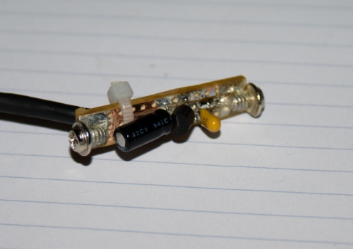
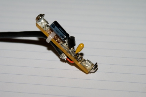
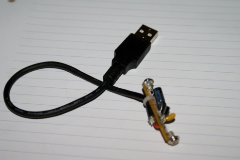
I really like my E3, it gives my HD555 a much needed bass boost… But, it eats loads and loads of batteries, so i decided to make a power supply for it, but I also wanted to keep case intact, so i can still use it with batteries. So I made a power supply that can go into battery compartment. It is based around LP2950 LDO 3.3 V voltage regulator. I decided to go for the 3.3V since the op amp in the hart of Fiio is made for 1.2-3.5V. The whole thing, is in my case powered from USB, but you can connect it to any voltage up to 30V. Here is how it turned out:
Note that the whole thing fits into battery compartment…
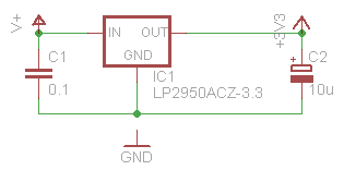
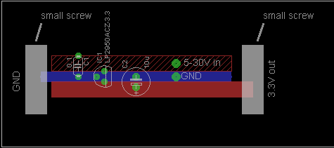
Here is the ultra simple schematic…
And here is the simple board layout, note that it is created on piece of proto board I had laying around. Sorry for a bit poor graphics, i guess i’m just to lazy to start illustrator to draw it better (so I drew it in eagle 🙂 ):
You can of course use any other 1.2 – 3.3 voltage regulator with same pinout (a lm317 in to-92 package, perhaps)…
The masterpiece works :). There is no audible noise, hum or anything else that is not suposed to be there and the amplified sound is exactly the same as before. Regulator emits little to no heat and op amp remains as cool as before, so there is no worries of destroying it. However, when I pluged it into my laptop (insted of my PC), certian noise was audible (probably due it’s poor voltage regualtion, and digital – analog ground separation), so i also made a veresion that is powerd from old Nokia charger, it of course also works just as well…
If you have any questions, feel free to ask…
Converting 29USD ET AVR board to 60+ USD wiring compatible board
We all love arduino, don’t we? And we love it because it’s cheap, flexible, has great user support, because it’s opensoruce (so we don’t feel bad about all the pirate software we stole J ) and so on. But arduino has it’s disadvantages as well, for me that is mostly a low pin count (yes, you zcan use port expanders, but that’s still not the same as having natively high pin count). Arduino’s older bigger brother wiring is using the same programming language, but is based on ATmega128 instead ATmega 168. That means that you get 53 pins instead of 11, and 128kb (instead of 16kb) of memory for your programs (check this site for details). The downside? It costs 60+ $ (ok, a worthy upgrade in US, but in EU this comes closer to 100€ with postage, and that is whole army or arduinos … ). So what I will show you is how to convert cheapest (to my knowing) atmega128 board http://futurlec.com/ATMEGA_Controller.shtml) to be wiring compatible.
Hardware:
Part list:
- · ET AVR controller board
- · 32khz crystal
- · 14 Contact IDC Socket Connector (http://futurlec.com/Connectors/IDCC14.shtml)
- · Switch (optional)
- · Led (optional)
- · Resistor (optional)
Tools:
- · Everything you need for some light soldering
- · Some sort of programmer (you can use the one that is sold at futurlec, otherwise just Google around a bit)
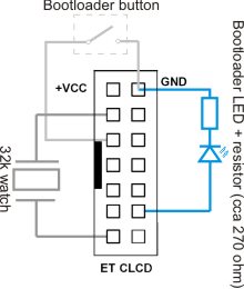
Most of the more expensive ATmega128 boards do not need any hardware modifications to run wiring, but this one is missing 32khz watch crystal, so we need to add it (unlike arduino, wiring will not operate without it, because it uses it as main clock, for time keeping etc..). When we are at it we will also add a bootloader switch and a status led for it. Note that these two components are not need, you can simply install time based bootloader to use instead of button based one and led is only for indication.
To avoid unnecessary hustle with creating pcb for those 3 simple components will simply put them around connector that plugs into ETCLCD port. Take a look at schematics below:
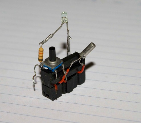
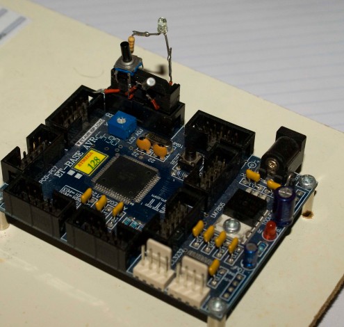
I assume you have already worked with this kind of connectors and that you have basic soldering skills, so I will not go into details on how to build it (if you are having problems you can mail me, or ask in the comments). Basically you just stick wires into connector, clamp it together, solder components and hot glue everything together (or put it into shrink tube, or use your imagination).
Second step: software (bootloader).
Before we can use the wiring we need to program our AT mega with appropriate bootloader. You can find source code for wiring bootloaders on this site: http://www.avride.com/article/wiring/ . Bellow are my two versions of bootloader.
First one is button based, that means that you have to hold bootloader button down while you reset the board to enter bootloader, also note that when you are in bootloader the led will turn on (PG0 will be high). Note that this is V1 bootloader.
BOOTLOADER DOWNLOADSecond one is time based, that means that you do not need to press bootloader button, instead every time you reset the board it will enter the bootloader for 8sec and than the normal program will start. Downside is of course that you will have to wait 8 sec every time you turn on the board (very very annoying when you are programming or debugging it). Note that this is V1 bootloader.
Programming fuses:
If you are using PonyProg for programming, here is the screenshot of the appropriate fuses.
Otherwise here is copy/past from wiring bootloader site:
Fuse setting is same as Wiring Board
Extended: 0xFF
High: 0xCC
Low: 0x3F
Important bit fuse
Boot Flash size 1024 words : BOOTSZ=10
Boot Reset vector enable : BOOTRST=0
CKOPT=0
BOD at 4.0V, : BODLEVEL=0
BOD enable : BODEN=0
Ext. crystal/resonator High Freq.; Start-up time 16K CLK + 64ms. : CKSEL=1111 SUT=11
Watchdog disable: WDTON=0
OCD disable: OCDEN=0
JTAG disable: JTAGEN=0
SPIEN enable: SPIEN=0
A quick note on bootloaders, I was unable to use V2 bootloader source code, if any1 succeeds please contact me.
Everything should be ready now, connect your brand new wiring clone to computer via RS232 port (yeah I know, it’s not usb but it’ll do), start up wiring, select correct COM port, select firmware version V1 and try to upload some simple blinking sketch.
About ports and pin numbering:
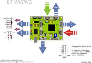
The problem is that the layout on the ET ATmega board is completely different than the one on the wiring board, so how do you know which pin is which? Just check the bellow diagram and everything will be crystal clear (I hope). Now go and play with your new toy, make something great, publish it under some OpenSource license and feel good about yourself.
Notes on using other boards:
You can of course any other ATmega128 board, as long as it is working at 16mhz, and has 32khz watch crystal. For pin mapping just check schematics on the official wiring site.
Update:
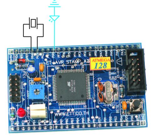
If you are converting a ET-AVR stamp board, you should solder the crystal between PG3 and PG4, as illustrated. The led is of course optional and should be tied between PG0 and GND. You should use a time based bootloader, to avoid the need of a button. Because stamp board doesn’t have RS232 converter u will have to use external(just google TTL UART to RS232 (or USB) ) and you have to connect it to PE0 (receive) and PE1 (transmit) pins. Note that I don’t have any of these boards, so this is untested.
