Converting 29USD ET AVR board to 60+ USD wiring compatible board
We all love arduino, don’t we? And we love it because it’s cheap, flexible, has great user support, because it’s opensoruce (so we don’t feel bad about all the pirate software we stole J ) and so on. But arduino has it’s disadvantages as well, for me that is mostly a low pin count (yes, you zcan use port expanders, but that’s still not the same as having natively high pin count). Arduino’s older bigger brother wiring is using the same programming language, but is based on ATmega128 instead ATmega 168. That means that you get 53 pins instead of 11, and 128kb (instead of 16kb) of memory for your programs (check this site for details). The downside? It costs 60+ $ (ok, a worthy upgrade in US, but in EU this comes closer to 100€ with postage, and that is whole army or arduinos … ). So what I will show you is how to convert cheapest (to my knowing) atmega128 board http://futurlec.com/ATMEGA_Controller.shtml) to be wiring compatible.
Hardware:
Part list:
- · ET AVR controller board
- · 32khz crystal
- · 14 Contact IDC Socket Connector (http://futurlec.com/Connectors/IDCC14.shtml)
- · Switch (optional)
- · Led (optional)
- · Resistor (optional)
Tools:
- · Everything you need for some light soldering
- · Some sort of programmer (you can use the one that is sold at futurlec, otherwise just Google around a bit)
Most of the more expensive ATmega128 boards do not need any hardware modifications to run wiring, but this one is missing 32khz watch crystal, so we need to add it (unlike arduino, wiring will not operate without it, because it uses it as main clock, for time keeping etc..). When we are at it we will also add a bootloader switch and a status led for it. Note that these two components are not need, you can simply install time based bootloader to use instead of button based one and led is only for indication.
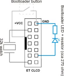
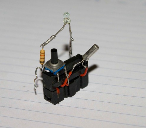
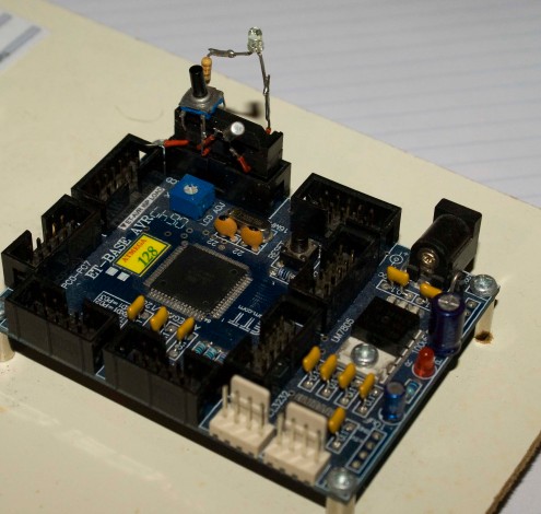
To avoid unnecessary hustle with creating pcb for those 3 simple components will simply put them around connector that plugs into ETCLCD port. Take a look at schematics below:
I assume you have already worked with this kind of connectors and that you have basic soldering skills, so I will not go into details on how to build it (if you are having problems you can mail me, or ask in the comments). Basically you just stick wires into connector, clamp it together, solder components and hot glue everything together (or put it into shrink tube, or use your imagination).
Second step: software (bootloader).
Before we can use the wiring we need to program our AT mega with appropriate bootloader. You can find source code for wiring bootloaders on this site: http://www.avride.com/article/wiring/ . Bellow are my two versions of bootloader.
First one is button based, that means that you have to hold bootloader button down while you reset the board to enter bootloader, also note that when you are in bootloader the led will turn on (PG0 will be high). Note that this is V1 bootloader.
BOOTLOADER DOWNLOADSecond one is time based, that means that you do not need to press bootloader button, instead every time you reset the board it will enter the bootloader for 8sec and than the normal program will start. Downside is of course that you will have to wait 8 sec every time you turn on the board (very very annoying when you are programming or debugging it). Note that this is V1 bootloader.
Programming fuses:
If you are using PonyProg for programming, here is the screenshot of the appropriate fuses.
Otherwise here is copy/past from wiring bootloader site:
Fuse setting is same as Wiring Board
Extended: 0xFF
High: 0xCC
Low: 0x3F
Important bit fuse
Boot Flash size 1024 words : BOOTSZ=10
Boot Reset vector enable : BOOTRST=0
CKOPT=0
BOD at 4.0V, : BODLEVEL=0
BOD enable : BODEN=0
Ext. crystal/resonator High Freq.; Start-up time 16K CLK + 64ms. : CKSEL=1111 SUT=11
Watchdog disable: WDTON=0
OCD disable: OCDEN=0
JTAG disable: JTAGEN=0
SPIEN enable: SPIEN=0
A quick note on bootloaders, I was unable to use V2 bootloader source code, if any1 succeeds please contact me.
Everything should be ready now, connect your brand new wiring clone to computer via RS232 port (yeah I know, it’s not usb but it’ll do), start up wiring, select correct COM port, select firmware version V1 and try to upload some simple blinking sketch.
About ports and pin numbering:
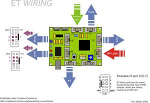
The problem is that the layout on the ET ATmega board is completely different than the one on the wiring board, so how do you know which pin is which? Just check the bellow diagram and everything will be crystal clear (I hope). Now go and play with your new toy, make something great, publish it under some OpenSource license and feel good about yourself.
Notes on using other boards:
You can of course any other ATmega128 board, as long as it is working at 16mhz, and has 32khz watch crystal. For pin mapping just check schematics on the official wiring site.
Update:
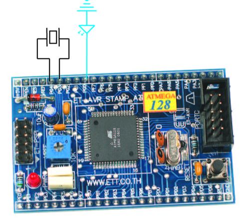
If you are converting a ET-AVR stamp board, you should solder the crystal between PG3 and PG4, as illustrated. The led is of course optional and should be tied between PG0 and GND. You should use a time based bootloader, to avoid the need of a button. Because stamp board doesn’t have RS232 converter u will have to use external(just google TTL UART to RS232 (or USB) ) and you have to connect it to PE0 (receive) and PE1 (transmit) pins. Note that I don’t have any of these boards, so this is untested.
Vaccumdiode said,
November 20, 2008 at 10:39 pm
That is cool!
Do you think that this will work with the ET AVR Stamp?
Cool!!
Vaccumdiode
jelengar said,
November 21, 2008 at 8:11 am
It should work, as long as you solder 32khz crystal between pins PG3 and PG4. You can add button and LED, but they are not neccesary (but handy, couse you dont have to wait for bootloader to boot). I will post an update on where exactly to solder the crystal on AVR stamp board.
Vaccumdiode said,
November 21, 2008 at 8:06 pm
Jelenger,
Sound great. It will save me some space and money on some project I have in mind.
Thank you
Vaccumdiode
ATmega Controller wiring upgrade - Hack a Day said,
November 28, 2008 at 2:18 am
[…] the ease of use of the Arduino, but wanted a much higher pin count. He set about converting the ATmega Controller for use with Wiring, the code that the Arduino IDE is based on. The ATmega128 in the controller features 53 pins as […]
xchip said,
November 28, 2008 at 12:45 pm
Why do you need a 32khz crystal?
chang said,
November 28, 2008 at 6:00 pm
hi, Jelenger
i have made my own wiring from ett-stamp and modify a new bootloader for mega64
you can see on that on my website(sorry that in thai language) but same you method 😀
ChANg
jelengar said,
November 28, 2008 at 6:41 pm
cahng, thank you for info and verification that this method works on stamp board as well.
@ xchip: although arduino is very similar to wiring there are differences in their inner working. One of major ones is how they handle time, and delay routines ( delay_ms() and mills() ). Wiring uses external 32khz crystal (also called watch crystal), so it can generate precise long delays, etc (arduino uses main crystal and internal divider).
Querystring » ATmega Controller wiring upgrade said,
November 28, 2008 at 9:46 pm
[…] the ease of use of the Arduino, but wanted a much higher pin count. He set about converting the ATmega Controller for use with Wiring, the code that the Arduino IDE is based on. The ATmega128 in the controller features 53 pins as […]
Vaccumdiode said,
November 28, 2008 at 10:19 pm
Jelengar,
I order the Atemel128 Stamp and I ordered a USB to TTL adapter. I have not loaded a bootloader before and I’ll give it a run and let you know what I end up with.
The Adapter I order uses the same chip that is on the wiring board for the USB. It should be a good fit and dropes the price way down for me.
Vaccumdiode
jelengar said,
November 28, 2008 at 10:27 pm
Hi, i hope you have a programmer at home (or access to one), otherwise you will not be able to burn your bootloader. I used the http://www.futurlec.com/ET-AVR_Stamp.shtml#Programmer but any programmer that can also program fuses should do. Google avr programmer for about 10^6 results on that topic 😉
Free of All » Blog Archive » ATmega Controller wiring upgrade said,
December 1, 2008 at 2:22 am
[…] the ease of use of the Arduino, but wanted a much higher pin count. He set about converting the ATmega Controller for use with Wiring, the code that the Arduino IDE is based on. The ATmega128 in the controller features 53 pins as […]
Vaccumdiode said,
December 1, 2008 at 4:14 pm
jelengar,
Why a 32 mhz crystal?
Vaccumdiode
jelengar said,
December 1, 2008 at 5:10 pm
check my response no.7… In short, 32khz crystal is required by wiring’s time handling facilities (mills(), and delay functions) and can not operate without it.
Thiyagarajan said,
December 24, 2008 at 11:55 pm
It is a great post. I am planning to go for ET-AVR modification. If I want to connect the button switch in this setup where can I connect it? Thanks for any suggestions.
Thiyagarajan said,
December 25, 2008 at 6:33 pm
Also is there a way to run the wiring scripts in ATmega 128 without a bootloader? We know that Arduino supports ATmega 8 and 168 without bootloaders.
Please see here:
http://www.arduino.cc/en/Hacking/OtherHardware
Is something similar possible with wiring environment with ATmega 128?
Thanks.
jelengar said,
December 25, 2008 at 8:30 pm
Of course it is possible, you should just flash your atmega with .hex created by Wiring IDE. However you still need to add 32khz crystal, as it is required by backend wiring libraries…
Nocturnal said,
January 4, 2009 at 9:10 am
I have a ET-AVR stamp, and I tried the conversion. It works great, though the bootloaders you provide did not work. However the ones on the site you linked for the source code
http://www.avride.com/article/wiring/
work just fine. I also wired in a bootloader switch, unfortunately there is no convenient nearby, so I ran a wire down to the ground pin for it.
samira said,
March 22, 2009 at 5:31 pm
Following your and “Khun” ChANg ( “Mr” in Thai language ) articles, I am able to install and setup my ETT-avr Stamp128 + ET-avr startKit V1 to run under “Wiring” environment.
It works fine.
Thanks
samira
pizza recipe said,
February 7, 2013 at 10:53 am
One thing that I never really comprehend is why some blog posts
are incredibly bad – and yours is undoubtedly not! Many thanks
for sharing a good post with folks!